Unlocking the Secrets of USB PCB Design: A Comprehensive Guide for 2024 and Beyond
At a time when digital transformation and technological evolution are of increasing significance, understanding and mastering USB Printed Circuit Board (USB PCB) design has become more vital than ever. This comprehensive guide is intended to demystify this realm, giving you all of the tools, principles, and insight required for effective navigation of this subfield of electronic engineering.
Chapter 1: Understanding USB PCBs – An Introduction
What exactly are USB PCBs? USB, or Universal Serial Bus, is a plug-and-play interface used by computers to communicate with peripheral and other devices. A USB PCB gets its name from its use of connectors connected via this standard on the board – though its design requires more than that! USB PCB design requires attention to high speed designs while adhering to protocol standards established for USB.
Chapter 2: USB PCB Design Principles and Concepts
As part of USB PCB design, many factors require careful consideration: aligning USB data lines, managing impedance, accounting for electromagnetic interference (EMI), etc. This chapter will discuss each of these elements chronologically while outlining why each factor is essential and how best to apply them in your designs.
Chapter 3: Focuses on best practices in USB PCB Design
Navigating USB PCB design can often seem like an endless maze, which is why we have assembled our selection of best practices to streamline this process. From considering board stackup early in the design process and optimizing trace routing to mastering differential pairs – these habits will not only enhance current projects but also any that come along in the future.
Chapter 4: Exploring the Advantages of USB PCBs
USB PCBs represent more than just a passing trend – they represent a transformative change to how devices connect and communicate with one another. Their benefits range from increased data transfer speeds, universal compatibility, increased power supply capacities, to increasing connectivity speeds – just some of many advantages that USB PCBs bring. In this chapter we explore these advantages further and discover their impactful contributions towards driving new opportunities, products, and potential.
Chapter 5: Emerging Trends in USB PCB Design
As we look towards 2024 and beyond, what trends will shape the landscape of USB PCB design? From USB 4’s rise to increased data transfer speeds and power supply capacities, we take a close look at these key developments so you can stay ahead of the curve.
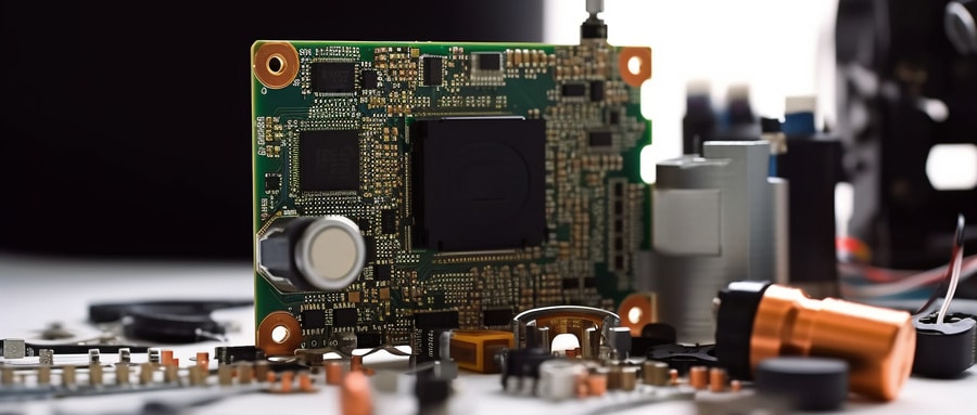
Conclusion of USB PCB Design Process
USB PCB design may be complex and technical, yet exciting all at the same time. As we venture into uncharted digital territory, this guide’s principles and practices will serve as your compass, helping guide you through all the challenges and rewards found within its ever-evolving landscape.
By providing you with everything from basic understanding to more in-depth discussions on best practices, benefits, and future trends for USB PCB designs, we hope this guide can assist in further improving them. No matter where your design journey may have led you now – with its details provided here progression should always be an assured outcome.
This comprehensive guide to USB PCB design serves as a useful resource for beginners as well as experienced professionals looking to understand, improve, and master this fascinating world of PCBs. Not only will it expand your knowledge base but it’ll equip you with practical information needed to navigate its ever-evolving frontiers of technology – this book may serve as your compass as you venture forth on this exciting journey of discovery that lies before us all!
FAQ:
- What is a USB Printed Circuit Board?
A USB Printed Circuit Board is a printed circuit board design that incorporates a universal serial bus (USB) interface. It allows electronic devices to communicate and share data. - How does a USB Printed Circuit Board work?
USB Printed Circuit Boards work as an interface for data transmission. It converts digital data into electronic signals, which are then transmitted through the USB connection. - How to design a USB Printed Circuit Board?
Designing a USB Printed Circuit Board involves several steps, including schematic design, layout design, component placement, trace routing, and finalizing the PCB design. - What software can I use to design a USB Printed Circuit Board?
There are various software options available for designing USB Printed Circuit Boards, such as Altium, Eagle, KiCad, and OrCAD. - What factors should I consider when designing a USB Printed Circuit Board?
When designing a USB Printed Circuit Board, consider factors such as the type of USB interface needed, the power requirements, the board size, the component placement, and the signal routing. - What is the role of impedance in USB Printed Circuit Board design?
Impedance matching in USB Printed Circuit Board design is crucial to prevent signal reflection, enabling efficient data transfer over the USB interface. - Can I manufacture a USB Printed Circuit Board at home?
Yes, you can, provided you have all the necessary equipment and materials. However, it may be more convenient and practical to work with a professional PCB manufacturing service. - What materials are commonly used in USB Printed Circuit Board manufacturing?
Common materials include copper for conductive layers, FR-4 fiberglass for the substrate, and solder mask for the protective layer. - What types of USB interfaces can a USB Printed Circuit Board support?
A USB Printed Circuit Board can support various types of USB interfaces like USB Type A, Type B, mini USB, micro USB, and USB Type C. - What are some common applications of Printed Circuit Boards?
USB Printed Circuit Boards are used in a wide range of devices such as computers, digital cameras, printers, smartphones, and numerous other consumer electronic devices.

